Beyond the Lines: Exploring the Unique Roles of Schematic Drawings and Wiring Diagrams in Electrical Engineering
While both schematic drawings and wiring diagrams are types of technical drawings used in electrical engineering, they serve different purposes and present information in distinct ways. Here are the key differences between schematic drawings and wiring diagrams.
Purpose
Schematic Drawing: Schematic drawings focus on representing the functional relationships between components in a circuit. They emphasize the logical connections and interactions, providing an overview of how the circuit works.
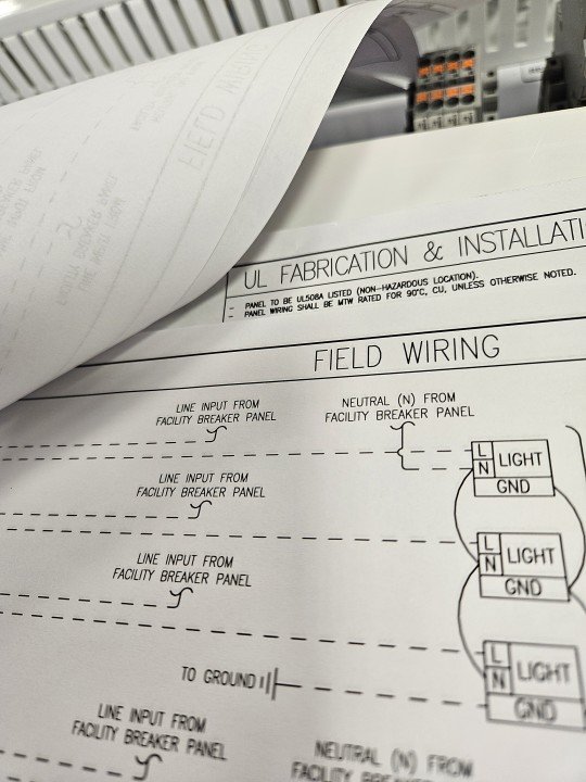
Wiring Diagram: Wiring diagrams, on the other hand, provide a more detailed view of the physical layout and connections of the components within a circuit. They are concerned with illustrating how the components are physically connected.
Level of Abstraction
Schematic Drawing: Schematics use abstract symbols to represent components and their connections. The emphasis is on the functionality and logical relationships between components rather than their physical appearance.
Wiring Diagram: Wiring diagrams use more realistic depictions of components and their physical placement. They show the actual arrangement of wires and components in the system.
Representation of Components
Schematic Drawing: Components are represented by standardized symbols, making it easier to understand the circuit's logical structure. It abstracts away the physical details of the components.
Wiring Diagram: Components are represented more realistically, often using pictorial representations or detailed images of the actual components. This helps in understanding the physical layout and connections.
Complexity
Schematic Drawing: Schematics are typically used for complex systems and circuits, providing a high-level representation of the overall functionality.
Wiring Diagram: Wiring diagrams are often used for simpler systems or for detailing the physical connections within a specific part of a larger system.
Summary
Schematic drawings focus on functionality and logical relationships, using abstract symbols, while wiring diagrams provide a detailed view of the physical connections and layout of components using more realistic representations. Both types of diagrams are crucial in understanding and designing electrical systems.
Fanatically Manufacturing Industrial Control Panels since 1958!
UL 508A, 698A, & NNNY Certified.